Gottwald AK 850-1 Scale 1:30
Motivation
The idea to create this crane came up in December 2003, I have been surfing around on the internet and seen some
huge LEGO cranes, created by other fellow LEGO builders. I started to wonder why I never have tried to build a
 huge Lattice boom crane. All the former mobile cranes, were all telescopic cranes, but there is a problem with
building telescopic booms in LEGO, since the bricks are thick and a telescopic boom therefore gets very heavy, and the
size is limited because of that.
Before I began to think about building a lattice boom crane, I have bought a book about mobile cranes written by Lothar Husemann, published by Motorbuch Verlag.
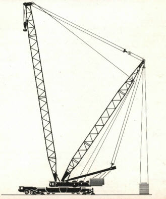
In this book there are a few pictures of the Gottwald AK850 mobile crane. It is a 850 ton mobile crane, with a maximum boom
length of 178 meters. It is one of the largest lattice boom mobile cranes ever built, and soon I knew that was the model
I wanted to built.
huge Lattice boom crane. All the former mobile cranes, were all telescopic cranes, but there is a problem with
building telescopic booms in LEGO, since the bricks are thick and a telescopic boom therefore gets very heavy, and the
size is limited because of that.
Before I began to think about building a lattice boom crane, I have bought a book about mobile cranes written by Lothar Husemann, published by Motorbuch Verlag.
In this book there are a few pictures of the Gottwald AK850 mobile crane. It is a 850 ton mobile crane, with a maximum boom
length of 178 meters. It is one of the largest lattice boom mobile cranes ever built, and soon I knew that was the model
I wanted to built.
First I created a "small" LEGO model of the crane, in the scale 1:80, read more about it here.
This crane was a succes, and I figured out that I had to get started with the big model of this crane very soon.
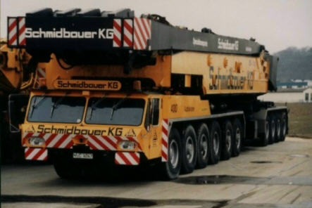
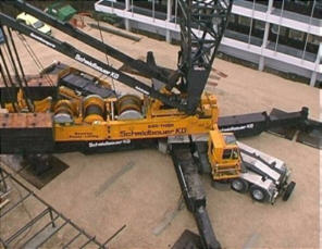
The real one
The Gottwald AK850 crane is produced in two version: AK850-1 and AK850-2. AK850-1 is the first version built, it
carried the whole superstructure, which resulted in a gross vehicle weight of 148 ton! Due to tightening of the control,
it was not approved to drive on the road in 1997, and in 1998 the crane was rebuilt by a special company in Nürnberg.
The superstructure was split in two parts, and the A-boom were dismounted. This model got the version number AK850-2.
The weight was reduced by 36 ton, and the crane could now be approved againg to go on the roads again.
The crane is equipped with a 113 meters main boom, or a combination of mainboom and luffing flyjib with a total of 178
meters.
Two AK850 cranes were built, one in version AK850-1 and one in version AK850-2, later rebuilt to AK912 with a larger capacity.
Hans Dieter Höcker has helped me with the fine images and data of the original crane. Dieter has made a very good CD with
a lot of images and data of a lot of Gottwald cranes. Go visit his homepage here, where you can by a CD with all the information and pictures.
Data
I choose to built the crane in scale 1:30 from the company Schmidbauer KG, Gräfelfing in Germany, since it was my goal to built a crane which looks like the real one
equipped with its full boom length, and in this scale it might be possible.
The data I have of the original crane is put here below.
 |

| Max capacity |
850 t |
|
| Main boom |
113 m |
|
| Fly jib |
95 m |
|
| Total height |
178 m |
|
| Engine |
M.A.N. 12 cylinder, 520 HP |
|
| Drive and stearing |
20x8x18 |
|
| Top speed |
62 km/h |
|
| Gross vehicle weight |
112 t |
|
| Total Counter weight |
516 t |
|
|
The LEGO model
From beginning I aimed to construct a very look a like model, I were inspired by other fellow LEGO constructors
on the internet, and
now I wanted to built a very lifelike model of a lattice boom crane in large scale.
The choise of scale is 1:30, since it thereby might be possible to built the crane with almost fully boom length
in this scale, and there are also some wheels which fit in this scale, 2695 and 2696.
Below I have descriped the details in construction the largest LEGO model I ever built.
Chassis
The chassis of a Gottwald AK-850 are made in 3 different parts. In the front is a module with 6 axles, drivers cabin
and the engine. In the middle is the turntable, where the outriggers are mount, and in the rear is put a module with
4 axles. My LEGO model chassis is made in one piece, since I first found out later the chassis could be seperated. But maybe
it will be implemented later.
Wheels and stearing
The chassis is built upon the large turntable in the middle, in front there are 6 turnable axles, behind
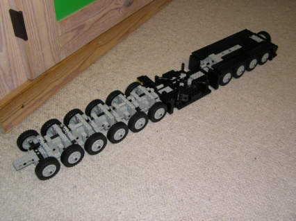 are 4 turnable axles. All the axles is steared by one single axle from front to end, connected with bushings to prevent slack.
The two axles in front and behind the turntable are controlled by gears with 8 tooths. The two next axles in front and the two rear axles are
controlled by gears with 14 tooths, and the two axle in front are controlled by gears of 16 tooths. In this way you can almost manage
to get the desired angle of all axles, when the crane goes around a curve, see the picture below.
are 4 turnable axles. All the axles is steared by one single axle from front to end, connected with bushings to prevent slack.
The two axles in front and behind the turntable are controlled by gears with 8 tooths. The two next axles in front and the two rear axles are
controlled by gears with 14 tooths, and the two axle in front are controlled by gears of 16 tooths. In this way you can almost manage
to get the desired angle of all axles, when the crane goes around a curve, see the picture below.
On the original crane you can control the axles individually which gives the possibility to drive almost sideways, only turn in front, or back, or turn
around the center. I havent implemented this function since it would take up to much space in the small chassis.
The wheels of the model are the LEGO 2695 and 2696
which also are used in the LEGO Model Team models, they fit in size, and they are almost correct in scale, and with the 12 studs wide body
the scale of 1:30 is almost perfect.
On the rear end of the model I have put the sparewheel, like on the original, the sparewheel are by gears of 1:4 coupled to the long axle
which control the stearing of the 10 axles.
The last part was to equip the model with lights, plates, mudguards and bumper.
Drivers cabin
In the front, you will find the drivers cabin, for driving the crane on roads. The drivers cabin is placed in front of all the axles to
create space for the superstructure.
In the drivers gabin I have placed two seets, one for the driver, and one for an assistant, a steering wheel and some instruments. On the roof
I have put some extra lights and horns.
Engine
Like the real crane, this model is also equipped with a 12 cylinder engine. Because of the size it is of course not functional, and only
built to look like the original. Under the ventilation plate you can see the engine. In front of the engine you can see 2 airtanks,
and from each site of the engine the exhaust is taken through cromium plate pipes and silencers.
The cromium parts are from the truck Black Cat.
Outriggers
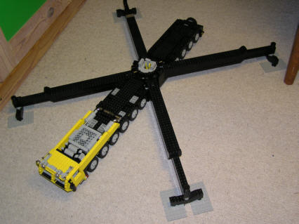
Between the 6 front axles and 4 rear axles the support for outriggers and turntable for carrying the whole cranes is placed.
The outriggers for this crane are so large and heavy that it is impossible to carry them on the crane itself
when it is transported, therefore they can be seperated from the crane and transported on 2 seperate flatbed trucks.
The model is also equipped with four detachable outriggers. Each outrigger is equipped with an axle in the end,
and an axle in the bottom. By installing the outriggers first put the axle in the end into a hole under the turntable
and thereafther the vertical axle is forced through a hole below the outrigger on the crane. In the top of each
outrigger there is a small pressure plate, to give every outrigger a small angle downwards, which is set off by the large
weight of the whole crane.
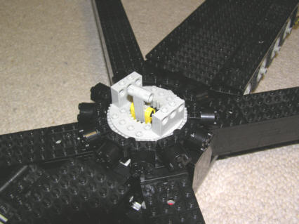
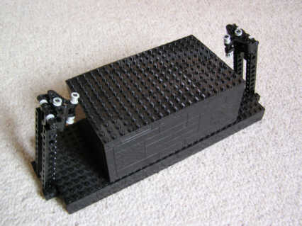
Turntable
Upon the outriggers the large turntable is placed, it has to be very strong since it has to carry the whole weight of the crane
and the load.
The former crane I have built, were all built on the large Technic turntable 2855 and 2856.
So is this crane, but it is improved a lot by make a rim of rollers around the turntable, like and axial roller bearing.
The rollers are made of round bricks 2x2, and joint by small hinges. Because of the dimension of the crane
it is impossible to reinforce the rim of rollers, put since it runs around the Technic turntable it holds the
circular form. Because of the rollers it is not possible to use the outer rim of the turntable to turn the crane
around.
Below I have put some more pictures of outriggers and turntable.
Pictures of the finished chassis.
Superstructure
I have chosen to build the superstructure in the version AK850-1, which mean not separated, because of the small size
it is difficult to find the necessary space for winches, motors and wires, when the superstructure on the same time has
to be very stable to handle the large pressure and forces from the crane. Therefore it would be almost impossible to create
the AK850-2 version.
Winches
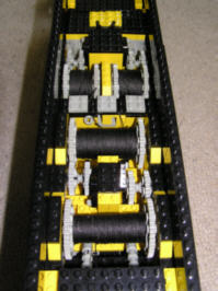
The most important element in the superstructure are the winches and the long wires which has to go on and off.
The winches has to take a lot of wires, in this model I use around 70 meters when the crane is put up to its full
height. All this wire the winches has to carry.
On the model I have put 4 winches, one for the A-bracket, one for the main boom with superlift, on for the luffing flyjib, and
one for the hoist. The winches are made of a normal Technic axle with round 2x2 bricks to reinforce the axle and
to avoid the very low gearing there would be if the wire was put direct on the thin axle.
In each end of the winch there is a large 40 tooth gear, which both works as a powerline and edge for the wire.
Wire
It took some time for me to find a good "wire" for this crane. The line has to be very thin, since 70 meters takes up
a lot of space, but meanwhile the line has to be very strong, and correct looking. I sought for some time for a weaved line,
since this kind of line do not twist when it is loaded. But I could not manage to find such thin weaved line, and I have
to use a line which is used for reparing fishing nets, very strong, thin and black.
The line has not given me any problem since it is most used with a lot of block which cant twist. Only the hoist has given me some problems
when the line is very long, and not that many lines for the hook.
Motors and gears
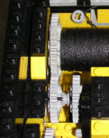
The motors to drive the winches are built in to the superstructure, I have used the new geared 9V motors for all the
4 winches, one for each. Two motors are placed in front, to drive the two small winches, and two motors in the back to drive
the two large winches.
The relation between motor and winches are 1:24:40 i.e. 1:40, which gives the sufficient linepull to raise the crane with
main boom and luffing flyjib.
Since the winches are that low geared to handle the load, it means they run very slowly, and it takes quite a long
time to pull 70 meters of wire in and out. Therefore I have made af neutral gear for each winch, which makes it possible
to manually put line on and off the winches, it saves a lot of time when setting up the crane.
Operator's cab
The crane operator also has to have a cabin. This is placed in the rear of the crane under transport, and can be
swung to the side when the crane is working.
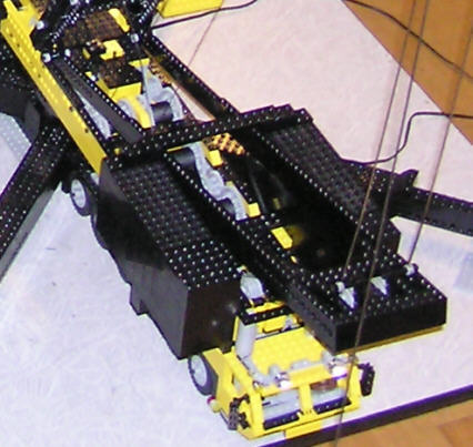
Counterweights
The counterweight is a very important part of a crane, alle cranes are equipped with some kind of counterweight.
There are very simple rules for lifting loads with a crane: The force the load puts on the crane, has to
be the same as the force the counterweight puts on the crane on the opposit site of the turntable.
On this crane the counterweight are placed in the rear of the superstructure. On the original you can put 206 tons
, on this model I have 2.9 kg for each site, a total of 5.8 kg.
The two counterweights are made of LEGO, filled with different kind of steel inside. Under the transport the counterweight
are transported on seperate trucks.
Fitting the main boom and superlift
The superstructure in this type of crane, is equipped with some heavy made bearings for the main boom and eventually
a superlift can be fitted.
By transportation it is only the bottom of either the main boom or superlift, and the A-bracket which are carried by the crane itself.
If the crane uses a superlift it is fitted in the most rear bearing, and the main boom is fitted in the front bearing.
The A-bracket
When the main boom is raised, it is raised with the help of the A-bracket, this part is carried by the crane during transport, and
it can be raised with hydraulic cylinders, when the crane is without load. Then it is coupled to the main boom, and by some heavy duty
winches and wires the A-bracket is pulled down again and the Main boom up in the air.
The A-bracket is also used to raise the superlift boom if this is used. The A-bracket is always equipped with
the buttom part of the main boom or superlift.
On my model the A-bracked is couplet to the superstructure by 12 wires through blocks.
Main boom
The main boom on a lattice boom crane, is like the name descripes the part that is always used, in a long og short
version.
Data
Data of the main boom for the original crane.
|
|
| Basic length |
23 m |
|
| Extensions |
6, 12 and 18 m |
|
| Max length |
113 m |
|
|
The bottom section
The first part of the main boom, is most of the time mount directly on the superstructure.
The bottom part carries the A-bracket, and is therefore always brought with the crane in transport.
If the crane is going to use a superlift then the main boom is mount on another seperate buttom piece, like
the other.
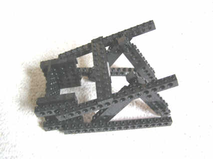
On my crane you will discover that the two buttom pieces are a little different. The one for the main boom itself
is not that strong, and fits on the crane by transportation. The other one is used with a superlift, and is made
a lot heavyer. From my experince from other cranes, I knew the biggest problem would be the sideways stability of the
crane, and the first part of the boom, the junction is a very important part of the crane.
I tried several constructions for the buttom piece, and the best of them, was made with some parts I newer knew
I should use again, it is the parts that are used for the two tracks of a robot in the set Cybermaster.
They turned out to bee extremely good for the purpose, they have a very heavy junction in the one end, and they are therefore
very usefull for the main boom.
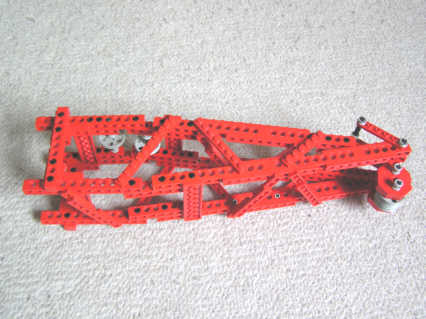
Extensions
The main boom are made with 3 extensions, each of them 60 cm long. They are made of 4 technic beams, one
in each corner, and some diagonal braces in all directions.
Topsection
The topsection of the main boom is made in two versions, the one is for a lift only with the main boom or superlift,
and the other is used for the flyjib.
In this configuration where it is only the main boom used, the topsection is primarily a frame for all the rollers
for the wire to the lifting hook.
Quy pins
When the crane is set up with the main boom itself, you need some pins between the end of the A-bracket and the end
of the main boom to transfer the load from the hook to the counterweights on the superstructure, these pins are called
quy pins. On the first version of the crane, I used some line, but they turned out not to be stiff enough, they got longer
when the crane was heavely loadede, and they were not stable enough.
Another solution was to made the quy pins of LEGO parts, but it is hard to find LEGO parts, which can handle
pulling forces, and if they can, they are very large, looks clumsy, and the weight is big.
My solution was to use some thin metal wires, used for welding. They are about 60 cm long, and in the end I have made an
eye for a small Technic bushing, and can therefore be put together with small technic beams. I think the result is
good, they looks real, and the stability of the crane is improved a lot.
Hook for hoist
When the crane is going to lift a load, it uses a hook with a lot of wires and blocks, if the load is heavy
you use a lot of wires, and similar if the load is light you only use a few wires. Sometimes you use different
hooks for different loads.
In the bottom of this site I have made a link with description of the setup with main boom, named S-configuration.
Superlift
If you want to lift a very heavy load with the crane, or very heigh in the air, you need more
counterweight and stability, it is not possible to add that much more counterweight to the superstructure, since
it would put too much load in this. The counterweight has to be mooved a longer to the rear and mount on
something else than the superstructure itself.
Therefore you use a 'Superlift', it is working with another second boom which are placed in an almost vertical
position, but to the rear of the superstructure.
The boom is typically 30-40 meters long, and the top of this boom is connected to the top of the main boom. In
this boom the extra maxilift ballast are hung in some quy pins. It can be put on the ground and raised if the
crane has to turn.
Data
Data of the Superlift of the original crane.
 |
|
| Basic length |
35 m |
|
| Extensions |
6, 12 and 18 m |
|
| Maxilift ballast |
250 t |
|
|
Bottom section
As mentioned in the section above descriping the main boom, then the bottom part is normally used for the main
boom, but is changed and used for the superlift if this is mounted. And another second bottom piece is used for the
main boom. The superlift is therefore always coupled to the A-bracket, and this is used to raise the superlift.
The superlift is in this model built the same way as the main boom.
Extensions
The basic length of the superlift is 35 meters, but in some places it can be necessary to use some extensions
of 6, 12 or 18 meters. The extensions are the same as used in the main boom.
Topsection
The topsection on the superlift, is a rather complicated part of the boom. Here are placed quy pins for the maxi-lift ballast,
the A-bracket, and a huge set of rollers for the wires raising the main boom. Those 3 things has to bee very heavy made
to handle the large forces from the crane and load, (on this crane the force is more than 20 kg in each direction, with full boom length).
There is 8 wires for raising the main boom.
Rear quy pins
The quy pins for the maxi-lift ballast and A-bracket, are the same as the one used for the main boom described above.
But they are fitted in different length to match the length of the superlift, and the ballast is in the right distance
from ground.
Maxi-lift ballast
The advantage of the ballast compared to the counterweight on the superstructure is the distance from the turntable.
Normally this distance is about doubled, that means the ballast only has to bee half the weight that would be necessary
to put on the superstructure.
.
You can put 250 ton of ballast on the superlift, which could be compared to about 500 ton on the superstructure.
In the bottom of this site I have made a link with description of the setup with superlift, named SDB-configuration.
Luffing Flyjib
If you want to lift a load very high up in the air, or very long horizontal above a tall building, it is good
to be able to luff the outer part of the boom. For this purpose you use a 'Luffing Flyjib' it is just an extension
to the main boom, but it can be luffed with a system of brackets and wires.
Very often the superlift are also used when using the flyjib, since the load of the cranes are very large, and the
superlift can bring those forces down.
Data
Data of the Flyjib for the original crane.
 |
|
| Basic length |
29 m |
|
| Extensions |
6, 12 and 18 m |
|
| Max length |
95 m |
|
|
The bottom part and the A-brackets
The flyjib is coupled to the end of the main boom, with a special joint. In the joint two A-brackets are mount
which handle the forces from the load to the bottom of the main boom. One of the A-brackets are mount on the
main boom, and the other is mount on the flyjib.
The junction between the main boom and the flyjib, is one of the hard part to built, it is hard to make a
stiff, stable and light construction.
Extensions
The flyjib can be extended like the main boom and superlift with sections of 6, 12 or 18 meters. These sections
are a bit smaller in dimentions than those used for the main boom. It is due to the smaller load and forces on
the flyjib, since the load is often smaller.
Waggon for the flyjib
When the crane is raised with the flyjib, the flyjib is pulled along the ground, for that manouvre a small waggon is used to carry the flyjib.
Setup
Below I have made a description of the three main configuration the crane can be used with.
Data
Below I have listed the final data of the model.
 |
|
| Max capacity |
Not tested |
|
| Max height |
5.2 m |
|
| Main boom |
2.6 m |
|
| Flyjib |
2.6 m |
|
| Gross vehicle wieght |
3.0 kg |
|
| Max counterweight |
16.9 kg |
|
| Used wire |
app. 70 m |
|
Conclusion
Finally a little conclusion to this project. It is absolutely the largest and most comprehensive
LEGO project until this date. Not my project with most bricks, but it is the most time-consuming project
but probably its due to the creation of this website at the same time, and the time I have used for
setup of the model for photografy.
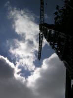
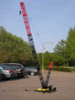
From beginning I aimed for building the model with the full boom lengt, i.e. 178 meters, which compared
to this scale is about 5.95 meters. I didnt reach this target, but anyway I am satisfied with 5.20 meters.
The height is limitid of the missing stability, not from strength. Im sure the LEGO could carry another meter,
but the stability in the bricks are missing, and the width of the turntable is only 9.2 cm, and it have
to carry the whole height of the crane.
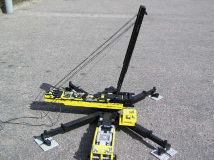
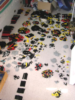
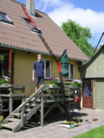
The picture to the right is absoulutely the last picture of the model, and as you see, it it now demolished
and ready for new projects in the future.
A few more details of the model:
 |
|
| Length |
75 cm |
|
| Width |
9.2 cm |
|
| Construction time |
app. 250 hours |
|
| Used bricks |
6676 - (yep, I did count them) |
|
)
)
)
)
)
)
)
)
)
)
)
)
)
)
)
)
)
)
)
)
)
)
)
)
)
)
)
)
)
)
)
)
)
)
)
)
)
)
)
)
)
)
)
)